
Int J Chem Res, Vol 9, Issue 3, 6-8Review Article
APPLICATION OF WASTE HEAT RECOVERY BOILERS FOR ENERGY CONSERVATION IN LEAD SMELTING OPERATIONS IN DARIBA MINES
REKHA TRIPATHI
Department of Applied Sciences, Maharaja Surajmal Institute of Technology, New Delhi-110058, India
*Corresponding author: Rekha Tripathi; *Email: [email protected]
Received: 21 Feb 2024 Revised and Accepted: 13 Apr 2025
ABSTRACT
Objective: This paper examines strategies for waste heat recovery, focusing on high-temperature waste gases produced by boilers, kilns, ovens, and furnaces.
Methods: The design and operation of waste heat recovery boilers (WHRB) are explored including fume condition, technical parameters and water supply quality with an example of a system that recovers heat from off-gases to generate steam.
Results: WHRB system is highly efficient, generating 12 tons of heat per hour in the form of steam by recovering waste heat from off-gases. The efficiency of such a system typically depends on the temperature and volume of the waste gas, the quality of the heat exchanger, and the design of the WHRB.
Conclusion: By capturing waste heat, industries can save substantial amounts of primary fuel, reduce energy consumption, and lower operational costs. Additionally, the paper demonstrates the positive environmental impacts of such systems, including reduced energy usage and lower emissions, contributing to enhanced sustainability and energy efficiency in industrial operations.
Keywords: Dariba mines, WHRB, Energy conservation
© 2025 The Authors. Published by Innovare Academic Sciences Pvt Ltd. This is an open access article under the CC BY license (http://creativecommons.org/licenses/by/4.0/)
DOI: http://dx.doi.org/10.22159/ijcr.2025v9i3.271 Journal homepage: https://ijcr.info/index.php/journal
INTRODUCTION
Waste heat is heat that is generated in a process by way of fuel combustion or chemical reaction and then “dumped” into the environment even though it could still be reused for some useful and economic purpose. The essential quality of heat is not the amount but rather its “value." The strategy of how to recover this heat depends in part on the temperature of the waste heat gases and the economics involved. A large quantity of hot flue gases is generated from Boilers, Kilns, Ovens and Furnaces.
If some of this waste heat could be recovered, a considerable amount of primary fuel could be saved. The energy lost in waste gases cannot be fully recovered. However, much of the heat could be recovered, and loss can be minimized by adopting some measures [1-4].
Depending upon the type of process, waste heat can be rejected at virtually any temperature, from that of chilled cooling water to high-temperature waste gases from an industrial furnace or kiln. Usually the higher the temperature, the better the quality and more cost-effective the heat recovery. In any study of waste heat recovery, it is absolutely necessary that there be some use for the recovered heat. Typical examples of use would be preheating combustion air, space heating, or preheating boiler feed water or process water. With high-temperature heat recovery, a cascade system of waste heat recovery may be practiced to ensure that the maximum amount of heat is recovered at the highest potential [5, 6]. An example of this technique of waste heat recovery would be where the high-temperature stage was used for air preheating and the low-temperature stage used for process feed water heating or steam raising [7]. This study based on strategies for waste heat recovery, focusing on high-temperature waste gases produced by boilers, kilns, ovens, and furnaces with the help of waste heat recovery boilers (WHRB).
MATERIALS AND METHODS
Waste heat recovery boiler operation
Furnace waste heat boiler system
The waste heat boiler is used to cool the high-temperature off-gas from the SKS furnace, fully recover the heat of the off-gas and recover part of the metal dust, which can create favorable conditions for further dust collection.
The high temperature off gas from the SKS furnace will go through the waste heat boiler, dust collection system, and acid-making system.
The steam produced in the waste heat boiler will be supplied for domestic and production use by the pipe network.
Fume condition of the furnace waste heat boiler
Off gas input of waste heat boiler: 24055 Nm3/h (normal cubic meters per hour), Inlet gas temperature:900±100 °C, Dust content (outlet): 179 g/m3 (gram per cubic meter).
Main technical parameters of the waste heat boiler for furnace
Working pressure: 4.0 Mpa (MegaPascal), Rated evaporating capacity: ~10 t/h (tons per hour), Rated temperature: 251.8 °C, Water supply temperature: 104 °C, Temperature of discharged fume: 360±20 °C
Water supply quality for SKS furnace waste heat boiler
Hardness:≤2 μmol/l (micromole per liter), Electric conductivity : <5μs/cm(micro siemens per centimetre), SiO2:<0.1 mg/l,PH:8.8-9.2, Phosphate radical:5-15 mg/l(milligram per liter)
Structure of the waste heat boiler for the furnace
The boiler is composed of an uptake flue, aradiation chamber, and aconvection area. Positive circulation is used and the waste heat boiler is located outdoor. The heating surface and pipe column are made of seamless steel pipes [8, 9].
The bottom of the uptake flue of the waste heat boiler is connected with the outlet of the furnace and is composed of the heating surface in the membrane wall structure. The spacing between the pipes is 80 mm. The curved offtake transition piece is used for the seal of the fume when furnace rotates and is located at the bottom of the uptake flue. An emergency off-gas exit chimney is also arranged on the heating surface. The straight part of the uptake channel is high and the melting dust can flow to the smelting furnace by gravity which can reduce the accumulation of ash on the heating surface. The temperature of the uptake channel outlet gas is about 700~800 °C.
The radiation cooling space of waste heat boiler and convective region is in a horizontal arrangement. The radiation cooling space is composed of the heating surface in the membrane wall structure and the spacing between pipes is 80 mm. The off-gas will go through the radiation-cooling space to the convective area. The outside wall of the convective region is of all membrane structure and the spacing between pipes is 100 mm. In the flow direction of the off gas, there are Evaporator Bundles. The Evaporator Bundles are made of boiler steel pipes. After going through the convection zone, the temperature will drop to about 360 °C and the off gas will be discharged from the waste heat boiler and go into the dust collection system. The boiler drum of the waste heat boiler is located at the roof platform of the SKS furnace plant [10].
Rapping devices are provided in the waste heat boiler, which can effectively remove the accumulated dust on the heating surface in time and ensure the proper running of the boiler. Dust scraper conveyor is installed under the hopper of the waste heat boiler. The dust from the waste heat and the dropped clinker under the impact of the rapping devices will be sent to the dust collection section by the chain conveyor.
Thermal power system of the furnace waste heat boiler house
The de-mineralized water will be sent to the de-mineralized water tank and then pumped to the Deaerator in which the oxygen will be removed. Then, it will be stored in the water tank. The deoxidized water will be pumped into the waste heat boiler drum in, which it will be mixed with boiler water. Then it will go to the hot water circulating pump via down comer. After being pressurized by the hot water circulating pump, the circulating water will be sent to the heating surfaces of the waste heat boiler in which it will be heated. Then, it will return to the drum. The returned steam and water mixture will be separated in the drum. The separated water will continue to circulate while the saturated steam will be led out of the drum and supplied to the steam network of the Dariba Smelter Complex at battery limit [12].
Arrangement in the furnace waste heat boiler house
Regular blowdown tank, heat exchanger pump, hot water circulating pump, online analyzer, demineralized water tank and de-mineralized water pump are on level ±0.00m of the auxiliary span in the waste heat boiler house. Low-pressure dosing device, high-pressure dosing device, and deaerator and tank for de-aerating water are on level+21.00m.
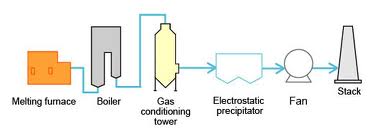
Fig. 1: Sequence of pollution control equipment
The horizontal section of the waste boiler for the furnace is located at the +28.50m level of the boiler house.
RESULTS
High-temperature heat recovery
The following table 1 gives temperatures of waste gases from industrial process equipment in the high temperature range. All of these result from direct fuel-fired processes.
Table 1: Temperatures of waste gases released from industrial processes
| Types of device | Temperature, °C |
| Nickel refining furnace | 1370 –1650 |
| Aluminum refining furnace | 650–760 |
| Zinc refining furnace | 760–1100 |
| Copper refining furnace | 760– 815 |
| Steel heating furnaces | 925–1050 |
| Copper Reverberatory furnace | 900–1100 |
| Open-hearth furnace | 650–700 |
| Cement kiln (Dry process) | 620– 730 |
| Glass-melting furnace | 1000–1550 |
| Hydrogen plants | 650–1000 |
| Solid waste incinerators | 650–1000 |
| Fume incinerators | 650–1450 |
The following table 2 indicates the off gas composition of daribalead smelter
Table 2: Off gas composition
| Gas | SO2 | SO3 | O2 | H2O | CO2 | N2 |
| V % | 11.47 | 0.62 | 10.71 | 17.03 | 5.26 | 54.92 |
Efficiency of the WHRB system
The Waste Heat Recovery Boiler (WHRB) system is highly efficient, generating 12 tons of heat per hour in the form of steam by recovering waste heat from off-gases. The efficiency of such a system typically depends on the temperature and volume of the waste gas, the quality of the heat exchanger, and the design of the WHRB.
The efficiency of the WHRB system could be quantified in terms of its thermal efficiency, which measures how well the system converts waste heat into useful steam. A high thermal efficiency would imply that a significant portion of the waste heat is being utilized for steam generation.
DISCUSSION
Recovering waste heat can be conducted through various heat recovery technologies [11]. Similar type of work was studied using WHRB associated with a bottom-blown smelting furnace using experimental and numerical methods to solve its slagging, low-temperature corrosion, and air or fume leakage problems [12].
The recovery of waste heat reduces the need for additional fuel or energy input for heating purposes. This results in lower energy usage and reduced operational costs. Environmental advantages are achieved through a decrease in emissions, as there is less dependence on fossil fuels for heat production.
By capturing waste heat, the WHRB system enhances the overall energy efficiency of the facility. This leads to greater sustainability by reducing energy loss and lowering operational carbon emissions [13]. The implementation of waste heat recovery systems, like WHRB, can aid in meeting environmental standards and corporate sustainability objectives. Additionally, a decrease in the use of non-renewable resources promotes long-term energy sustainability, leading to a more environmentally conscious industrial operation.
CONCLUSION
The WHRB system serves as an effective solution for energy recovery, generating considerable amounts of steam from the recovered waste heat. This steam is efficiently used for heating purposes, leading to energy savings, financial benefits, and positive environmental impacts. Nevertheless, ongoing monitoring and system optimization may reveal additional opportunities for enhanced efficiency and sustainability.
ACKNOWLEDGEMENT
The authors acknowledge the contributions of authorities of Dariba mines and Dept. of Environmental Science, S. S. Jain Subodh P. G. College Jaipur.
FUNDING
Nil
AUTHORS CONTRIBUTIONS
All authors have contributed equally
CONFLICT OF INTERESTS
The author declares no conflict of interest
REFERENCES
Rosen MA, Dincer I. Waste heat recovery. Energy. 2001;26(6):559-64.
Saidur R, Reza M. Energy recovery from waste heat: a review. Energy Rep. 2013;12:18-25.
Alabi WO, Baheta AT, Liu H. Review of waste heat recovery systems for industrial processes. Renew Sustain Energy Rev. 2017;67:1491-505.
Dincer I, Rosen MA. Exergy: energy. Environ Sustain Dev. 2013.
Adewuyi YG, Boso DG. Industrial waste heat recovery systems: a review. Renew Sustain Energy Rev. 2016;59:961-70.
Lund H, Moller B. Waste heat recovery in industrial applications: technologies and economic perspectives. Energy. 2008;33(4):463-9.
US Department of Energy (DOE). Waste heat recovery: technology and opportunities in U. S. Industry: United States Department of Energy Industrial Technologies Program; 2015.
Nyemba WR, Mushanguri I, Chinguwa S, Mbohwa C. Waste heat and energy recovery system from smelter off-gas for a platinum processing plant. In: proceedings of the 2017 International Conference on Industrial Engineering and Operations Management (IEOM) Bristol, UK; 2017.
Christodoulides P, Agathokleous R, Aresti L, Kalogirou SA, Tassou SA, Florides GA. Waste heat recovery technologies revisited with emphasis on new solutions, including heat pipes and case studies. Energies. 2022;15(1):384. doi: 10.3390/en15010384.
Ishaq H, Dincer I, Naterer GF. Exergy and cost analyses of waste heat recovery from furnace cement slag for clean hydrogen production. Energy. 2019 Apr;172:1243-53. doi: 10.1016/j.energy.2019.02.026.
Jouhara H, Khordehgah N, Almahmoud S, Delpech B, Chauhan A, Tassou SA. Waste heat recovery technologies and applications. Thermal Science and Engineering Progress. 2018 Jun;6:268-89. doi: 10.1016/j.tsep.2018.04.017.
Zhang D, MA T. Study on slagging in a waste heat recovery boiler associated with a bottom blown metal smelting furnace. Energy. 2022 Feb 15;241:122852. doi: 10.1016/j.energy.2021.122852.
Bauman A, Hartman P. Waste heat recovery for the cement industry. World Cem. 2014;45(6):34-40.